loading...

IndustrialBlog

Alex بازدید : 71 جمعه 25 تیر 1400 نظرات (0)

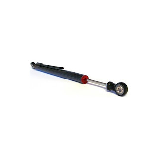
The measuring instrument called a potentiometer is essentially a voltage divider used for measuring electric potential (voltage); the component is an implementation of the same principle, hence its name.

To answer the question of what is linear potentiometer, first, let us see what are the different parts of this potentiometer. A linear taper potentiometer is usually made up of three pins that adjust to a flow of voltage, and produce a regulated voltage output relevant to its sliding components.

Parallel circuits are similar to the smaller blood veins that branch off from an artery and then join in a vessel to return blood to the heart. Now imagine two wires, each as an artery and a vein, that are connected to each other with some smaller wires. These smaller wires have the same voltages applied to them, but different amounts of current flow through them based on the individual wires’ resistance.

A circuit composed solely of components connected in series is known as a series circuit; likewise, one connected completely in parallel is known as a parallel circuit. Many circuits can be analyzed as combination of series and parallel circuits, along with other configurations.

In forward biasing, the external voltage supply is applied across the PN-junction diode. This voltage cuts the potential barrier and provides a low resistance way to the flow of current. The meaning of the forward bias is the connection of the positive region to the p-terminal of the supply, while the negative region is joined to the n-type of the device. To read more about these topics, you can use the references mentioned below.

References:

https://en.wikipedia.org/wiki/P%E2%80%93n_junction#Reverse_bias

https://www.linquip.com/blog/ultimate-guide-what-is-linear-potentiometer/

https://www.youtube.com/

https://www.linquip.com/blog/differences-between-forward-reverse-biasing/

https://en.wikipedia.org/wiki/Potentiometer

https://www.linquip.com/blog/differences-between-series-and-parallel-circuits/

Alex بازدید : 115 جمعه 25 تیر 1400 نظرات (0)

 linear potentiometer

A potentiometer is a three-terminal resistor with a sliding or rotating contact that forms an adjustable voltage divider If only two terminals are used, one end and the wiper, it acts as a variable resistor or rheostat.

Linear potentiometers have unique features to ensure long trouble-free life in the harshest of environments from motorsport to structural monitoring, from measuring linear position or displacement in a wide variety and broad range of manufacturing and process equipment. 

Series and parallel circuits

Two-terminal components and electrical networks can be connected in series or parallel. The resulting electrical network will have two terminals and can participate in a series or parallel topology. Whether a two-terminal "object" is an electrical component or an electrical network is a matter of perspective. This article will use "component" to refer to a two-terminal "object" that participates in the series/parallel networks. But what are the differences between series and parallel circuits?

Series and Parallel Circuit_ Close circuits have a complete path for current to flow in a loop. An open circuit does not have a closed-loop, which means that it’s not operative. A short circuit is a low-resistance path, usually made accidentally, that bypasses some parts of a circuit. A short circuit can occur when two bare wires in a circuit meet each other.  Read more

Forward Bias vs. Reverse Bias

In forward bias, the positive terminal of the battery is connected to the p-type material and the negative terminal is connected to the n-type material so that holes are injected into the p-type material and electrons into the n-type material. The electrons in the n-type material are called majority carriers on that side, but electrons that make it to the p-type side are called minority carriers. 

In reversed bias, there is a connection between the negative region and the positive terminal of the battery, and the positive region is joined to the negative terminal. The reverse potential boosts the strength of the potential barrier in this situation.

Alex بازدید : 56 جمعه 25 تیر 1400 نظرات (0)

 Turbines actually act as converters. They convert wind or sea energy into electrical energy and are considered as an alternative to non-renewable resources. There are different types of turbines, such as Impulse Turbine, wind turbine, etc.

Impulse Turbine

In these turbines, the static pressure inside the runner is constant, and the turbine runner is at atmospheric pressure. The runner spins in the air, and the fluid is sprayed to the blades through the nozzle to exchange energy with the turbine. A jet nozzle or a series of nozzles directs the high-speed flow to the blades, which are usually in the shape of buckets or cups. Therefore, only pressure changes occur in the nozzles.

In the case of steam turbines, such as would be used for marine applications or for land-based electricity generation, a Parsons-type reaction turbine would require approximately double the number of blade rows as a de Laval-type impulse turbine, for the same degree of thermal energy conversion.

Francis Turbine

Francis turbines are primarily used for electrical power production. The power output of the electric generators generally ranges from just a few kilowatts up to 1000 MW, though mini-hydro installations may be lower. The best performance is seen when the head height is between 100–300 metres (330–980 ft).

rancis turbines are employed regularly in hydroelectric power plants. In these power plants, high-pressure water enters the turbine through the snail-shell casing (the volute). This movement decreases the water pressure as it curls through the tube; however, the water’s speed remains unchanged. Following the passing through the volute, the water flows through the guide vanes and is directed towards the runner’s blades at optimum angles.

Kaplan Turbine and Hydrokinetic Turbine

HK turbines have relatively simple designs without the need for a reservoir or spillway. Initial testing indicates the adverse environmental effects are minimal, and the simplicity of these designs results in low-cost installation and maintenance. Therefore, this simplicity makes these systems valuable in rural or remote areas. In the following figure, you can see the flow conditions of hydrokinetic turbines.

A Kaplan turbine is one kind of a propeller hydro turbine (particularly a reaction turbine) used in hydroelectric plants. Waterflow both in and out of Kaplan turbines through its rotational axis, which is called axial flow. The point that makes Kaplan turbines special is that the blades can change their demand to preserve maximum efficiency for various water flow rates. 

References:

https://www.linquip.com/blog/hydrokinetic-turbines/

https://www.youtube.com/

https://www.linquip.com/blog/kaplan-turbine/

https://www.energy.gov/

https://www.linquip.com/blog/what-is-francis-turbine/

https://www.ethosenergygroup.com/

https://www.linquip.com/blog/impulse-turbine-working-principle/

Alex بازدید : 124 جمعه 25 تیر 1400 نظرات (0)

You must have heard the name of the turbine by now, and when you hear the name of the turbine, you will see a picture of turbines that move with the wind. But there are different types of turbines, one of which is wind turbines, such as Hydrokinetic Turbine, Kaplan Turbine, Francis Turbine, Impulse Turbine. In this article, we will introduce several types of turbines.

Hydrokinetic Turbines

Hydrokinetic Turbines include clean sources of renewable energy that significantly reduce the carbon emissions of off-grid sites, especially when relying on diesel fuel.

Hydrokinetic turbines produce a base load for the microgrid power systems. The portability of the system reduces the need for costly infrastructure. read more

Francis Turbine

The Francis turbine is a type of water turbine. It is an inward-flow reaction turbine that combines radial and axial flow concepts. Francis turbines are the most common water turbine in use today and can achieve over 95% efficiency.

These turbines can be used for heads as low as 2 meters and as high as 300 meters. Additionally, these turbines are beneficial as they work equally well when positioned horizontally as they do when they are oriented vertically. more information

Kaplan Turbine

The Kaplan turbine is a propeller-type water turbine which has adjustable blades. It was developed in 1913 by Austrian professor Viktor Kaplan, who combined automatically adjusted propeller blades with automatically adjusted wicket gates to achieve efficiency over a wide range of flow and water level.

Main parts of Kaplan Turbine as follows:

  • Scroll casing,
  • Guide vane mechanism,
  • Draft tube, and
  • Runner blades

Impulse Turbine

Generally, Hydro turbines are classified into two groups based on how the energy is exchanged between the fluid and the turbine: impulse turbines and reaction turbines. Impulse turbines operate based on the change of velocity vectors. In general, the potential energy of the water based on the height of the waterfall is converted into kinetic energy by one or more nozzles and then water hits the turbine blades at high speed causing the turbine to spin and consequently generates electricity.

Impulse turbines do not require a pressure casement around the rotor since the fluid jet is created by the nozzle prior to reaching the blades on the rotor.

Alex بازدید : 59 جمعه 25 تیر 1400 نظرات (0)

 Centrifugal Compressor is one of the types of compressors. In this post, we talked about how it works, its types, and comparing it with several other compressors.

The radial compressor is also called a centrifugal compressor. This kind of dynamic compressor has a radial design. They operate at constant pressure and any changes in the external conditions will affect the performance of these compressors.

Centrifugal compressors, sometimes called radial compressors, are a sub-class of dynamic axisymmetric work-absorbing turbomachinery.

They achieve a pressure rise by adding kinetic energy/velocity to a continuous flow of fluid through the rotor or impeller.  

Types of  Centrifugal Compressor

  • Multi-Stage Compressor

Multi-stage compressors are among different types of centrifugal compressors. As the name suggests, this compressor has been designed to pass the gas through multiple stages for diverse purposes. Multi-stage compressors are used when a single-stage compressor can’t keep up with the desired pressure requirements. This is because a single-stage compressor, as mentioned above, has only one impeller.

The simple explanation regarding “how does a centrifugal compressor work?” would be that they transform the velocity and the kinetic energy in the diffuser into the pressure energy.

There is a rotating impeller inside centrifugal compressors that has radial blades and the center of this impeller receives the air that is pushed by centrifugal force toward the center.

Differences Between Axial Compressor & Centrifugal Compressor:

  • Axial compressors are very expensive while centrifugal compressors are cheaper and have a wider operating range.
  • The mass flow rate in centrifugal compressors is less than 15 Kg/s and in the axial compressors is very large (more than 100 Kg/s).
  • Axial compressors operate more efficiently (about 94%) than centrifugal compressors (about 87%).

Differences Between Rotary & Reciprocating Compressors

  • Efficiency
  1. The efficiency of the rotary compressor is nearly 100%.
  2. The efficiency of the reciprocating compressor is less than 100%.

References:

https://www.linquip.com/blog/the-differences-between-rotary-reciprocating-compressors/

https://en.wikipedia.org/wiki/Centrifugal_compressor

https://www.linquip.com/blog/radial-compressor/

https://www.energy.gov/

https://www.linquip.com/blog/differences-between-axial-compressor-centrifugal/

https://www.ethosenergygroup.com/

https://www.linquip.com/blog/how-does-centrifugal-compressor-work/

https://www.britannica.com/

https://www.linquip.com/blog/types-of-centrifugal-compressor/

Alex بازدید : 62 جمعه 25 تیر 1400 نظرات (0)

In this article, we will introduce several types of compressors and explain the differences between them. Stay with us.

First we introduce the Centrifugal Compressor and then we review the Centrifugal Compressor Work. We will also introduce the types of Centrifugal Compressor.

A compressor is a mechanical device that increases the pressure of a gas by reducing its volume. An air compressor is a specific type of gas compressor.

Compressors are similar to pumps: both increase the pressure on a fluid and both can transport the fluid through a pipe. 

Centrifugal compressors, sometimes called radial compressors, are a sub-class of dynamic axisymmetric work-absorbing turbomachinery.

Centrifugal compressors are considered as a dynamic compressor type that has a radial design.  These compressors work with a constant pressure unlike the ones working at a constant flow. Plus, any changes in the external conditions affect the performance.

Types of Centrifugal Compressor

Centrifugal Compressor generally consists of 2 categories:

  • Single Stage Compressor
  • Multi-Stage Compressor

Single-stage compressors are among the popular types of centrifugal compressors available on the market. This type has a single impeller for directing the air or other gases for its specific purpose. The single-stage compressor also contains a diffuser and connected guide vanes.

But what is axial compressor vs centrifugal compressor?

An axial compressor is a gas compressor that can continuously pressurize gases. It is a rotating, airfoil-based compressor in which the gas or working fluid principally flows parallel to the axis of rotation, or axially. 

Some of the differences between them are:

  • Centrifugal compressors are easier to design and manufacture compared to axial compressors.
  • Contrary to centrifugal compressors, axial flow compressors do not change the direction of the gas.

radial compressor

radial compressors is actually another name for Centrifugal compressors. A radial compressor contains radial blades on its rotating impeller and the air is drawn into the center of this unit. The centrifugal force pushed the air into the center. The air’s radial movement inside these compressors will raise the pressure, resulting in the generation of kinetic energy.

rotary compressor vs reciprocating compressor

A reciprocating compressor or piston compressor is a positive-displacement compressor that uses pistons driven by a crankshaft to deliver gases at high pressure.

  • Size
  1. The size of the rotary compressors is smaller than the reciprocating compressor for the same discharge.
  2. The size of the reciprocating compressor is bulky and larger than the rotary compressor for the same discharge. 

read more

Alex بازدید : 101 جمعه 25 تیر 1400 نظرات (0)

 The motor is one of the most important parts of electrical equipment. There are different types of engines and we have talked about them in previous articles. In this article, we will talk about Induction Motor and examine one of its types.

An induction motor or asynchronous motor is an AC electric motor in which the electric current in the rotor needed to produce torque is obtained by electromagnetic induction from the magnetic field of the stator winding. An induction motor can therefore be made without electrical connections to the rotor. An induction motor's rotor can be either wound type or squirrel-cage type.

based on the construction and starting method, the single-phase induction motor is categorized into the four types of Split Phase, Capacitor Start, Capacitor Start Capacitor Run, and Shaded Pole. In the following sections, we will elaborate on each of these types of single-phase induction motors.

A commutator is a rotary electrical switch in some motors that supplies current to the rotor. It consists of a cylinder composed of multiple metal contact segments on the rotating armature of the machine. Two or more electrical contacts called "brushes" made of a soft conductive material like carbon press against the commutator, making sliding contact with successive segments of the commutator as it rotates, supplying the current to the rotor. The windings on the rotor are connected to the commutator segments.

A commutator itself is a split rotary ring, typically made of copper, with each segment of the ring attached to each end of the armature coil that is used in some types of electric motors and electrical generators whose job is to periodically reverse the current direction between the rotor and the external circuit.

References:

https://www.linquip.com/blog/types-of-induction-motor/

https://en.wikipedia.org/wiki/Induction_motor

https://www.gm.com/

https://www.linquip.com/blog/single-phase-induction-motor/

https://www.ethosenergygroup.com/

https://www.linquip.com/blog/commutator-motors/

Alex بازدید : 60 جمعه 25 تیر 1400 نظرات (0)

 In previous articles, we talked about the types of engines. In this article, we will introduce and review Single-Phase Induction Motor, Commutator Motors, and also Types of Induction Motor. Join us and read this article.

Induction motor

An induction motor or asynchronous motor is an AC electric motor in which the electric current in the rotor needed to produce torque is obtained by electromagnetic induction from the magnetic field of the stator winding.

There are mainly two types of induction motor. This classification is based on what power supply induction motors are fed with. Single-phase induction motors and three-phase induction motors are the two main types of induction motors. 

One of the types of induction motors is single-phase induction motor. The two main components of the single-phase induction motor are the stator and rotor. As you may know and  perceive from the name, the Stator is the stationary part of this motor. On the other hand, the rotor is the rotating component of the motor. the single-phase alternating supply reaches to the stator winding. more information

Commutator Motors

An electric motor is an electrical machine that converts electrical energy into mechanical energy. Most electric motors operate through the interaction between the motor's magnetic field and electric current in a wire winding to generate force in the form of torque applied on the motor's shaft. Electric motors can be powered by direct current (DC) sources, such as from batteries, or rectifiers, or by alternating current (AC) sources, such as a power grid, inverters or electrical generators. One of the types of electric motors is Commutator Motors.

As you may know, The operating principle of DC motors is on the basis of the mutual interaction between the magnetic field of an armature rotating and the magnetic field of a fixed stator. 

Alex بازدید : 86 جمعه 25 تیر 1400 نظرات (0)

We are going to talk about Differences Between Motor and Engine. We will first define the engine.

 A motor capacitor, such as a start capacitor or run capacitor  is an electrical capacitor that alters the current to one or more windings of a single-phase alternating-current induction motor to create a rotating magnetic field.

“Motor” is originated in the Classical Latin movere, “to move.” It first mentioned the propulsive force, and later, to the person or system that moved something or caused the movement.

The word engine derives from Old French engin, from the Latin ingenium–the root of the word ingenious. Pre-industrial weapons of war, such as catapults, trebuchets and battering rams, were called siege engines, and knowledge of how to construct them was often treated as a military secret. The word gin, as in cotton gin, is short for engine. “Engine” is from the Latin root: mental powers, character, intellect, talent, or cleverness. 

A Capacitor Start Motors is a single phase Induction Motor that employs a capacitor in the auxiliary winding circuit to produce a greater phase difference between the current in the main and the auxiliary windings.

The permanent magnet synchronous motors working principle is similar to the synchronous motor. The principle of operation is based on the interaction of the rotating magnetic field of the stator and the constant magnetic field of the rotor. It depends on the rotating magnetic field that generates electromotive force at synchronous speed. 

You can get more information about engines by reading the following links.

References:

https://www.linquip.com/blog/what-is-capacitor-start-induction-motor/

https://en.wikipedia.org/wiki/Motor_capacitor

https://www.energy.gov/

https://www.linquip.com/blog/differences-between-motor-and-engine/

https://www.gm.com/

https://www.linquip.com/blog/permanent-magnet-synchronous-motors/

Alex بازدید : 62 جمعه 25 تیر 1400 نظرات (0)

 In this post, we want to talk about Permanent Magnet Synchronous Motors and Capacitor Start Induction Motor. After introducing and reviewing each, we will examine the difference between motor and engine.

Permanent Magnet Synchronous Motors

First, we define the synchronous motor. A synchronous electric motor is an AC motor in which, at steady state, the rotation of the shaft is synchronized with the frequency of the supply current; the rotation period is exactly equal to an integral number of AC cycles. 

The Permanent Magnet Synchronous Motor (PMSM) is an AC synchronous motor whose field excitation is provided by permanent magnets. The permanent magnet synchronous motors are very efficient, brushless, very fast, safe, and give a high dynamic performance. Due to their advantages, permanent synchronous motors have many applications and find use in several fields.

Permanent Magnet Synchronous Motor (PMSM) is brushless and has very high reliability and efficiency. Due to its permanent magnet rotor, it also has a high torque with a small frame size and no rotor current. 

Capacitor Start Induction Motor

motor capacitor, such as a start capacitor or run capacitor (including a dual run capacitor)is an electrical capacitor that alters the current to one or more windings of a single-phase alternating-current induction motor to create a rotating magnetic field.

A Capacitor Start Motors is a single phase Induction Motor that employs a capacitor in the auxiliary winding circuit to produce a greater phase difference between the current in the main and the auxiliary windings. The capacitor start motor has a cage rotor and has two windings on the stator. They are known as the main winding and the auxiliary or the starting winding.

Differences Between Motor and Engine

By Wikipedia definition:An engine or motor is a machine designed to convert one form of energy into mechanical energy.

But what is the difference between motor and engine?

Motor” is originated in the Classical Latin movere, “to move.” It first mentioned the propulsive force, and later, to the person or system that moved something or caused the movement. 

“Engine” is from the Latin root: mental powers, character, intellect, talent, or cleverness. In its journey through the French language and into English, the term came to mean contrivance, ingenuity, and trick or malice. “

تعداد صفحات : 5

اطلاعات کاربری
  • فراموشی رمز عبور؟
  • آرشیو
    آمار سایت
  • کل مطالب : 42
  • کل نظرات : 0
  • افراد آنلاین : 1
  • تعداد اعضا : 0
  • آی پی امروز : 1
  • آی پی دیروز : 9
  • بازدید امروز : 3
  • باردید دیروز : 7
  • گوگل امروز : 0
  • گوگل دیروز : 0
  • بازدید هفته : 10
  • بازدید ماه : 3
  • بازدید سال : 1,082
  • بازدید کلی : 4,520