Everything about Gas Turbine
Gas turbine type can be considered as a highly important factor, for each type has its different applications. A gas turbine is a type of internal combustion engine. The engine can be considered as an energy conversion device as it converts energy stored in the fuel with beneficial mechanical energy into the shape of rotational power. As a professional network in the area of industrial equipment, we invite you to read this guide about gas turbine type at Linquip, find more useful information about the working principle of gas turbines, their applications, and learn about compressors and combustor types.
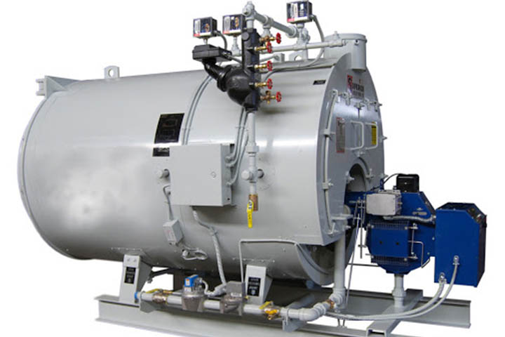
A gas turbine, also called a combustion turbine, is a type of continuous and internal combustion engine. The main elements common to all gas turbine engines are:
- an upstream rotating gas compressor
- a combustor
- a downstream turbine on the same shaft as the compressor.
The SGT5-8000H was the very first air-cooled H-class gas turbine on the market. More than 750,000 fired hours of operational experience make it the most reliable and tested H-class gas turbine technology available today. With a power output of 450 MW in simple cycle, or 665 MW in combined cycle operation, and a combined cycle efficiency of 61%, it is among the most efficient and powerful gas turbines in commercial operation, with low operating and lifecycle costs. read more

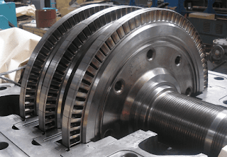
How do gas turbine parts go together?
By looking at a gas turbine, you can see the combustion section, one of the very important gas turbine parts, is between the compressor and the turbine flow direction. The fuel and the air are combined and burned in this way. Then, the hot exhaust passes the turbine and leaves the nozzle. We can consider two important roles performed by the nozzle. It is designed to make thrust by accelerating thrust generation via heat exhaust gas. Then the nozzle controls the engine’s mass flow.
The basic operation of the gas turbine is a Brayton cycle with air as the working fluid : atmospheric air flows through the compressor that brings it to higher pressure ; energy is then added by spraying fuel into the air and igniting it so that the combustion generates a high-temperature flow ; this high-temperature pressurized gas enters a turbine, producing a shaft work output in the process, used to drive the compressor ; the unused energy comes out in the exhaust gases that can be repurposed for external work, such as directly producing thrust in a turbojet engine, or rotating a second, independent turbine (known as a power turbine) that can be connected to a fan, propeller, or electrical generator. click here

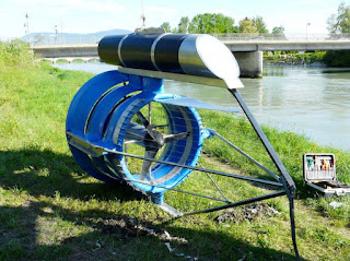
Solar battery
A rechargeable battery, storage battery, or secondary cell, (or archaically accumulator) is a type of electrical battery which can be charged, discharged into a load, and recharged many times, as opposed to a disposable or primary battery, which is supplied fully charged and discarded after use. It is composed of one or more electrochemical cells. The term "accumulator" is used as it accumulates and stores energy through a reversible electrochemical reaction. Rechargeable batteries are produced in many different shapes and sizes, ranging from button cells to megawatt systems connected to stabilize an electrical distribution network. Several different combinations of electrode materials and electrolytes are used, including lead–acid, zinc-air, nickel–cadmium (NiCd), nickel–metal hydride (NiMH), lithium-ion (Li-ion), and lithium-ion polymer (Li-ion polymer).
Knowing the right features of the best solar batteries enables you to choose the perfect one for your solar energy system. While evaluating the solar batteries, the essential things would be comparing battery’s power rating and capacity, its depth of discharge, warranty, and round-trip efficiency as well as the brand. click to read more information

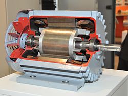
Industrial Gearbox
A transmission is a machine in a power transmission system, which provides controlled application of the power. Often the term 5 speed transmission refers simply to the gearbox that uses gears and gear trains to provide speed and torque conversions from a rotating power source to another device.
An industrial gearbox is an enclosed system that transmits mechanical energy to a transmission unit. The system slows down the speed and torque of rotation. Industrial gearboxes are different from standard gearboxes, as the former needs a long, stable life and safety factor for most of the drives. To control speed and torque and convert it functionally, an industrial gearbox transmits mechanical power into a driving tool. In contrast to mass gearboxes, industrial gearboxes can handle multiple tasks at extremely high speeds over a long period.
more information in this link: https://www.linquip.com/blog/general-equipments/industrial-gearbox/

Refrences:
https://www.linquip.com/blog/gas-turbine-type-applications/
https://new.siemens.com/
https://en.wikipedia.org/


 Differences Between forwarding and Survey Reverse Biasing and Linear Potentiometer
 What is Drift Eliminator 101 ?